Safe Motion Module - Safe DRIVE
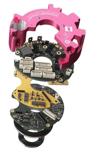
1. Technical Specifications
Technical Specifications :
2. Connectors Overview
Connectors and pinout
Synapticon documentation :
Mating parts
Connector details and mating part number :
3. User instructions and tips
-
Initial SMM configuration , system identification and re-tuning:
The units will be delivered with an initial tuning for the velocity and position PID controllers.
Nevertheless, such default tuning might not be suitable for your application and a retuning will be necessary.In order to perform the system identification and the tuning of the actuators, the safety motion module needs to have an initial configuration. Otherwise, It will have a fault and the power stage of the drive will not be enabled.
More details in “Taking the drive into operation” section.
-
Configure the Interpolator:
The internal interpolator (Command interpolator) of the drive is configured to work with 1kHz cycle time controllers. If a slower cycle time will be used, the interpolator configuration must be changed to avoid possible hardware damage.
Command smoothing and Interpolation
-
Regenerative Energy
The actuator can act like a generator when gravity effects or deceleration drives the motor in generator mode and power is injected into the powerline.
This regenerated energy will cause a DC voltage increase and can damage the drive and other equipment sharing the same DC bus.
The drive has hardware protection mechanism and fault reaction when the DC voltage goes above 59V.
This protection might not be sufficient to prevent hardware damage, if the voltage increase is faster than the drive’s reaction time.
To prevent any over-voltage errors and make sure the system works correctly, make sure that the regenerative energy can be absorbed either by a battery (in battery powered applications) or burned through resistors (braking chopper or shunt resistors)
more information here :
4. Safety Functions and FSoE
Faults Handling
Non Safety related Drive Faults
The drive can show different errors through the standard CiA402 object 0x603F and also through the manufacturer specific object 0x203F.
We recommend using the manufacturer specific errors object 0x203F, it provides more detailed string based error.
Standard errors list:
Error codes thrown by the firmware
Manufacturer specific errors list:
Suggested remedies for hardware triggered errors:
Remedies for protection errors
Safety Motion Module related Faults
Safety faults will be reported in the Error report object Error Report Object as SMMDead, SMMFatal or SmmFxxnn.
xx: type of SMM fault:
-
IO: IO Failure
-
In : Internal Failure
-
Iv: Invalid Failure
-
Uk: Unknown Fault
nn: SMM fault ID: Check the table in the following link SMM Faults
IO failures can be acknowledged if the fault itself is gone. All other failures need a power cycle of the drive.
Safety functions
The following functions can be configured and used with the TUAKA DRIVE SAFETY version
5. Documentation requirements
Ensuring the safety of drive configurations is critically important.
All safety-related settings and configurations must be meticulously documented to maintain compliance and facilitate future reference.
This documentation should include detailed records of parameter settings, safety protocols, and any modifications made during the configuration process.
It is crucial to recognize that while the safety drive is an integral component, it alone does not guarantee the safety of the entire system.
Comprehensive safety measures and thorough documentation for all machine components are essential to achieve the overall system safety.
Additionally, proper documentation aids in troubleshooting, maintenance, and audits, providing a clear historical record of all safety-related configurations.
6. Taking the drive into operation
Safety Motion Module Configuration
The configuration of the Safe Motion Module can be done in 2 ways:
1- Via a Safety Master:
The download of the safety related parameters and configuration will be done on the Safety Master and it will not be saved inside the memory of the Safe Motion Module on the drive.
2- Via Safety Motion Module Wizard:
The safety motion module is configured through OBLAC Drives using the SMM setup wizard.
The safety related parameters are saved inside the Drive.
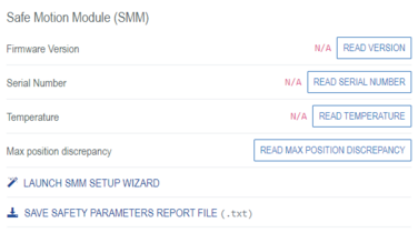
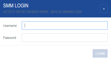
Username : free choose at the first time, 4 characters minimum
Password : SomanetSMM
Disabling the Safety Motion Module:OBLAC Drives is not a Safety Master and cannot process Safe Data packages via Fail Safe Over EtherCAT (FSoE)
It is necessary to disable the Safe fieldbus if you want to use OBLAC Drives for tuning.
After logging into the SMM setup wizard, follow the steps below:
Step1: Chose the option to configure via OBLAC
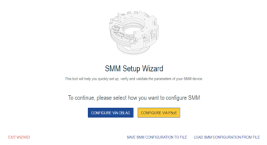
Step2: In general parameters set the Safe fieldbus to disabled

Step3: Continue to all next steps and verify the parameters and validate them.
Important: If you are disabling the fieldbus for an initial test and tuning of the actuator, there is no need to properly configure the safety function.
After tuning and testing of the drive, the Safety Specialist Engineer can then properly configure the safety functions and generate the report and make a proper documentation.
There are 2 ways of configuring the Safety Motion Module :
1- Via OBLAC Drives : The configuration of the Safety functions and parameters will be done in OBLAC and saved into the memory of the drive.
2- Via a Safety Master: The configuration of the different parameters of the safety functions will be written via a Safety Master.
Configuration via OBLAC Drives:
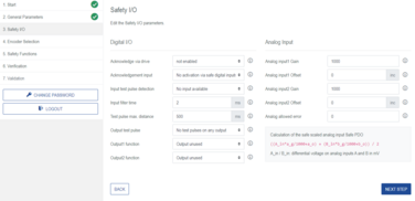
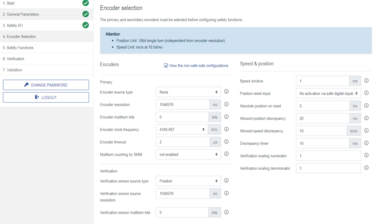
After entering the user name and the password, click on the configure via OBLAC option to start the configuration of the Safety Motion Module
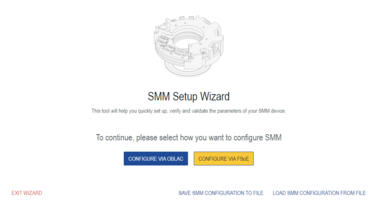
Step 1: General Parameters

Step 2: Safety I/O configuration
Step 3: Encoder selection

Step 4: Configure the safety Functions:
Step 5: Verification and validation of the Safe Motion Module configuration
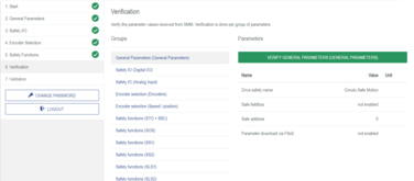

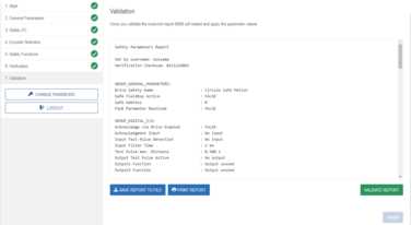
Source : ![]() Configuration via OBLAC Drives
Configuration via OBLAC Drives
-
Configuration via EtherCAT Safety Master.
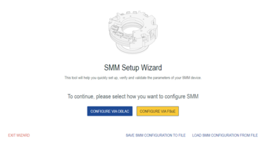

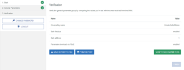
Source: Configuration via FSoE
System identification and tuning
Disabling the Safety Motion Module:
OBLAC Drives is not a Safety Master and cannot process Safe Data packages.
Therefore, it is necessary to disable the Safe bus to able use rotate the actuator with the tuning and configuration tool OBLAC Drives.
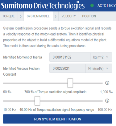
System identification
Velocity controller tuning
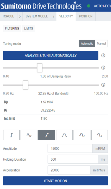
Position controller tuning
