smartris - Packaged-Drive Solution for AGV/AMR
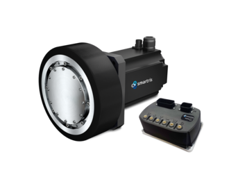
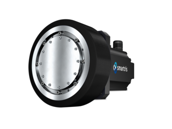
Combination of three smart components. \n A compact, integrated, and intelligent solution of : Gear + Servo Motor + Drive.
Complete Package Solution of Gear, Servo Motor and Drive
- Best fit for AGV or AMR driving
- Compact size achieved by in-wheel structure
- Easy installation and commissioning
- Filled with long-life grease (when shipped from factory)
- Maintenance free
- Customization available on request
| Type | ECO(S, M) / PRO(M, L) |
| Reduction Ratio | ECO: 21-29 / PRO: 22-30 |
| Output Type | Gear Output Shaft Rotation / Ring Gear Housing Rotation |
| Brake | PM(Permanent Magnet) Brake , Spring Brake |
| Feedback sensor | Resolver, Absolute Encoder, Safety Absolute Encoder |
| Safety Function | with STO(Safe Torque Off), without STO |

Key Customer Benefits
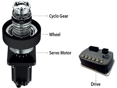
Servo Motor & Gear
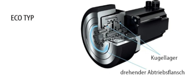
ECO Line
- Gear Output Shaft Rotation Design
- Cost efficient
- Ideal for light payloads and high-speed AGV
PRO Line
- Ring Gear Housing Rotation Design
- High radial loads
- Reduced overall dimension
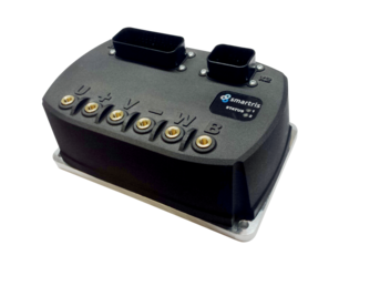
Drive
- Easy installation without additional PID tuning
- Easy to install with state machine profile suitable for all AGVs
- Specifically designed for prompt reaction in case of AGV emergency quick stop
Smartris installation example
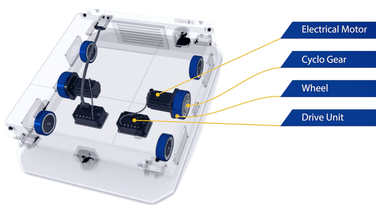
Reasons for choosing smartris
Packaged-Drive Solution
Three key components: gear, servo motor and drive in one package. It provides a highly reliable solution for various types of AGV/AMRs.
Support a wide range of performance
Multiple sizes and reduction ratios are available. The optimum product can meet wide variety of AGV/AMR’s specifications; total weight (payload + body weight) and max speed.
Variety of control modes
Speed control, position control and torque control are supported. These three control modes enable high-precision control.
Global Supply Chain
We provide high quality products to the global market by utilizing our manufacturing facilities around the world.
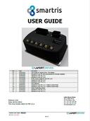
smartris Drive Compact
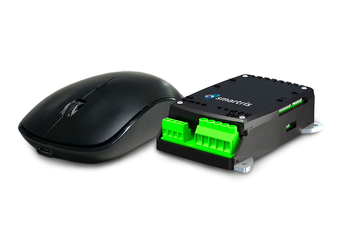
The new super-compact drive for AGV and AMR applications is four times smaller than the standard drive and is suitable for our ECO-S line. This makes it the perfect solution for companies that want to optimise the space requirements of their AGVs and AMRs without compromising on performance.
Gearmotor (Gear + Servo Motor)
Specifications
| Type | ECO | PRO | |||||||||
|---|---|---|---|---|---|---|---|---|---|---|---|
| Size | S | M | M | L | |||||||
| Voltage [VDC] | 48 | 48 | |||||||||
| Allowable Radial Load per Driving Wheel [N] | 1500 | 3000 | 6500 | 10000 | |||||||
| Reduction Ratio | 21 | 25 | 29 | 21 | 25 | 29 | 22 | 26 | 22 | 26 | 30 |
| Max Motor Speed [r/min] | 4500 | 4500 | 4500 | 3000 | |||||||
| Max Wheel Speed [r/min] | 214 | 180 | 155 | 214 | 180 | 155 | 205 | 173 | 136 | 115 | 100 |
| Rated Wheel Torque [N·m] | 16.0 | 18.9 | 18.9 | 39.3 | 40.4 | 40.5 | 39.3 | 40.4 | 84.7 | 87.5 | 80.3 |
| Peak Wheel Torque (2sec) [N·m] | 61.9 | 73.7 | 84.8 | 145 | 179 | 207 | 145 | 179 | 294 | 360 | 246 |
| Ambient Temperature [°C] | - 10 to 40 | - 10 to 40 | |||||||||
| Protection Class | IP54 (IP65) | IP54 (IP65) | |||||||||
| Thermal Class | Motor : 155 (F), Brake : F | Motor : 155 (F), Brake : F | |||||||||
| Output Type | Output Shaft Rotation | Ring Gear Housing Rotation | |||||||||
Note:
1. Allowable radial load of ECO type is a value at the position inside the output shaft end face.
2. Allowable radial load of PRO type is a value at the center of the gear part.
Dimensions
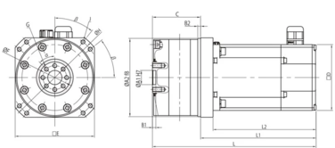
| Type | Size | L | L1 |
L2 |
ØA1 | ØA2 | B1 | B2 | C | □D | □E | ØF | G | ØH | J | K | ØN | M | α° | β° |
Mass [Kg] |
|---|---|---|---|---|---|---|---|---|---|---|---|---|---|---|---|---|---|---|---|---|---|
| ECO | S | (*) | (*) | (*) | 25 | 110 | 6 | 4 | 76 | 80 | 110 | 35 | 10-M6 | 130 | 4-M8 | - | - | - | 36 | 45 | 5.6 |
| M | 289 | 204 | 182 | 25 | 138 | 6 | 5 | 85 | 116 | 140 | 42 | 8-M8 | 160 | 8-M8 | - | - | - | 45 | 38.5 | 11.3 | |
| PRO | M | 282.5 | 199 | 182 | 145 | 123 | 27.5 | - | 28 | 116 | 160 | 134 | 4-M10 | 190 | 4-M10 | 4.1 | 140 | 23.5 | 30 | 45 | 14.5 |
| L | 309 | 213 | 196 | 182 | 155 | 38 | - | 30 | 142 | 196 | 170 | 4-M12 | 230 | 4-M12 | 4.78 | 175.8 | 32.8 | 30 | 45 | 24.5 |
Note:
1. The above dimensions are for the unit with PM brake.
2. (*) = The dimensions vary depending on the configuration of feedback sensor.
Resolver: L=235, L1=159, L2=143
Absolute encoder: L=249, L1=173, L2=157
3. Please inquire us for dimensions other than those listed above.
Drive
Specifications
| Type | ECO | PRO | |||||||||
|---|---|---|---|---|---|---|---|---|---|---|---|
| Size | S | M | M | L | |||||||
| Voltage [VDC] | 48 (30 to 60) | ||||||||||
| Rated Current [Arms] | 11.5 | 25.8 | 25.8 | 35.8 | |||||||
| Peak Current (2sec) [Arms] | 41.7 | 96.3 | 96.3 | 136.2 | |||||||
| Peak Current (10sec) [Arms] | 24.9 | 57.5 | 57.5 | 81.3 | |||||||
| Feedback sensor | Resolver, Absolute encoder, Safety absolute encoder | ||||||||||
| Communication Method | CANopen, Modbus | ||||||||||
| Digital Input | 4 Points/photocoupler (24V±20% 100mA) can be used with sink logic or source logic | ||||||||||
| Digital Output | 4 Points/photocoupler (24V±20% 7mA input impedance 3kΩ) can be used with sink logic or source logic | ||||||||||
| Analog Input | 1 point/±10V or 0 to10V (input impedance 10kΩ) | ||||||||||
| Analog Output | 1 point/0 to 10V max 1mA | ||||||||||
| Safety Function | with STO, without STO | ||||||||||
| Protection Class | IP54 | ||||||||||
| Certification | CE + UL | ||||||||||
Note:
1. (*) = We are planning We are planning conformity to Modbus LTU. Please inquire us about RS-232C for service tool.
2. Power cable and control cable are not attached.
Dimensions
Standard Configuration
| Standard Configuration | Other Option | ||||||
|---|---|---|---|---|---|---|---|
| EMEIA | Asia | ||||||
| Feedback sensor | Safety absolute encoder | Resolver | Absolute encoder, Incremental encoder | ||||
| Motor Cable (Power) | IP54 (1m) | IP64 (1m) | |||||
| Motor Connector (Power) | without | IP65 connection | |||||
| Brake | PM brake | Spring brake | |||||
| Safety Function | with STO | without STO | - | ||||
